Jewish code of conduct "Shulchan Aruch" about Christianity and attitude towards the goyim
(Published in Tel Aviv in 1958. Transmitted with minor abbreviations). Jews! Love each other, help each other...
Modern games use more and more graphic effects and technologies that improve the picture. However, developers usually don’t bother explaining what exactly they are doing. When you don't have the most powerful computer, you have to sacrifice some of the capabilities. Let's try to look at what the most common graphics options mean to better understand how to free up PC resources with minimal impact on graphics.
When any texture is displayed on the monitor not in its original size, it is necessary to insert additional pixels into it or, conversely, remove the extra ones. To do this, a technique called filtering is used.
Bilinear filtering is the simplest algorithm and requires less computing power, but also produces the worst results. Trilinear adds clarity, but still generates artifacts. The most advanced method that eliminates noticeable distortions on objects that are strongly inclined relative to the camera is anisotropic filtering. Unlike the two previous methods, it successfully combats the gradation effect (when some parts of the texture are blurred more than others, and the boundary between them becomes clearly visible). When using bilinear or trilinear filtering, the texture becomes more and more blurry as the distance increases, but anisotropic filtering does not have this drawback.
Given the amount of data being processed (and there may be many high-resolution 32-bit textures in the scene), anisotropic filtering is particularly demanding on memory bandwidth. Traffic can be reduced primarily through texture compression, which is now used everywhere. Previously, when it was not practiced so often, and the throughput of video memory was much lower, anisotropic filtering significantly reduced the number of frames. On modern video cards, it has almost no effect on fps.
Anisotropic filtering has only one setting - filter factor (2x, 4x, 8x, 16x). The higher it is, the clearer and more natural the textures look. Typically, with a high value, small artifacts are visible only on the outermost pixels of tilted textures. Values of 4x and 8x are usually quite enough to get rid of the lion's share of visual distortion. Interestingly, when moving from 8x to 16x, the performance penalty will be quite small even in theory, since additional processing will only be needed for a small number of previously unfiltered pixels.
Shaders are small programs that can perform certain manipulations with a 3D scene, for example, changing lighting, applying texture, adding post-processing and other effects.
Shaders are divided into three types: vertex shaders operate with coordinates, geometry shaders can process not only individual vertices, but also entire geometric shapes consisting of a maximum of 6 vertices, pixel shaders work with individual pixels and their parameters .
Shaders are mainly used to create new effects. Without them, the set of operations that developers could use in games is very limited. In other words, adding shaders made it possible to obtain new effects that were not included in the video card by default.
Shaders work very productively in parallel mode, and that is why modern graphics adapters have so many stream processors, which are also called shaders. For example, the GeForce GTX 580 has as many as 512 of them.
Parallax mapping is a modified version of the well-known bumpmapping technique, used to add relief to textures. Parallax mapping does not create 3D objects in the usual sense of the word. For example, a floor or wall in a game scene will appear rough while actually being completely flat. The relief effect here is achieved only through manipulation of textures.

The source object does not have to be flat. The method works on various game objects, but its use is desirable only in cases where the height of the surface changes smoothly. Sudden changes are processed incorrectly and artifacts appear on the object.
Parallax mapping significantly saves computer computing resources, since when using analogue objects with an equally detailed 3D structure, the performance of video adapters would not be enough to render scenes in real time.
The effect is most often used on stone pavements, walls, bricks and tiles.
Before DirectX 8, anti-aliasing in games was done using SuperSampling Anti-Aliasing (SSAA), also known as Full-Scene Anti-Aliasing (FSAA). Its use led to a significant decrease in performance, so with the release of DX8 it was immediately abandoned and replaced with Multisample Anti-Aliasing (MSAA). Despite the fact that this method gave worse results, it was much more productive than its predecessor. Since then, more advanced algorithms have appeared, such as CSAA.
Considering that over the past few years the performance of video cards has noticeably increased, both AMD and NVIDIA have again returned support for SSAA technology to their accelerators. However, it will not be possible to use it even now in modern games, since the number of frames/s will be very low. SSAA will be effective only in projects from previous years, or in current ones, but with modest settings for other graphic parameters. AMD has implemented SSAA support only for DX9 games, but in NVIDIA SSAA also functions in DX10 and DX11 modes.
The principle of smoothing is very simple. Before the frame is displayed on the screen, certain information is calculated not in its native resolution, but in an enlarged one and a multiple of two. Then the result is reduced to the required size, and then the “ladder” along the edges of the object becomes less noticeable. The higher the original image and the smoothing factor (2x, 4x, 8x, 16x, 32x), the less jaggies there will be on the models. MSAA, unlike FSAA, smoothes only the edges of objects, which significantly saves video card resources, however, this technique can leave artifacts inside polygons.
Previously, Anti-Aliasing always significantly reduced fps in games, but now it affects the number of frames only slightly, and sometimes has no effect at all.
Using tessellation in a computer model, the number of polygons increases by an arbitrary number of times. To do this, each polygon is divided into several new ones, which are located approximately the same as the original surface. This method allows you to easily increase the detail of simple 3D objects. At the same time, however, the load on the computer will also increase, and in some cases small artifacts cannot be ruled out.
At first glance, tessellation can be confused with Parallax mapping. Although these are completely different effects, since tessellation actually changes the geometric shape of an object, and does not just simulate relief. In addition, it can be used for almost any object, while the use of Parallax mapping is very limited.
Tessellation technology has been known in cinema since the 80s, but it began to be supported in games only recently, or rather after graphics accelerators finally reached the required level of performance at which it can be performed in real time.
For the game to use tessellation, it requires a video card that supports DirectX 11.
V-Sync is the synchronization of game frames with the vertical scan frequency of the monitor. Its essence lies in the fact that a fully calculated game frame is displayed on the screen at the moment the image is updated on it. It is important that the next frame (if it is already ready) will also appear no later and no earlier than the output of the previous one ends and the next one begins.

If the monitor refresh rate is 60 Hz, and the video card has time to render the 3D scene with at least the same number of frames, then each monitor refresh will display a new frame. In other words, at an interval of 16.66 ms, the user will see a complete update of the game scene on the screen.
It should be understood that when vertical synchronization is enabled, the fps in the game cannot exceed the vertical scan frequency of the monitor. If the number of frames is lower than this value (in our case, less than 60 Hz), then in order to avoid performance losses it is necessary to activate triple buffering, in which frames are calculated in advance and stored in three separate buffers, which allows them to be sent to the screen more often.
The main task of vertical synchronization is to eliminate the effect of a shifted frame, which occurs when the lower part of the display is filled with one frame, and the upper part with another, shifted relative to the previous one.
This is the general name for all the effects that are superimposed on a ready-made frame of a fully rendered 3D scene (in other words, on a two-dimensional image) to improve the quality of the final picture. Post-processing uses pixel shaders and is used in cases where additional effects require complete information about the entire scene. Such techniques cannot be applied in isolation to individual 3D objects without causing artifacts to appear in the frame.
An effect often used in game scenes with contrasting lighting. If one area of the screen is very bright and another is very dark, a lot of the detail in each area is lost and they look monotonous. HDR adds more gradation to the frame and allows for more detail in the scene. To use it, you usually have to work with a wider range of colors than standard 24-bit precision can provide. Preliminary calculations occur in high precision (64 or 96 bits), and only at the final stage the image is adjusted to 24 bits.
HDR is often used to realize the effect of vision adaptation when a hero in games emerges from a dark tunnel onto a well-lit surface.
Bloom is often used in conjunction with HDR, and it also has a fairly close relative - Glow, which is why these three techniques are often confused.

Bloom simulates the effect that can be seen when shooting very bright scenes with conventional cameras. In the resulting image, the intense light appears to take up more volume than it should and to “climb” onto objects even though it is behind them. When using Bloom, additional artifacts in the form of colored lines may appear on the borders of objects.
Grain is an artifact that occurs in analog TV with a poor signal, on old magnetic videotapes or photographs (in particular, digital images taken in low light). Players often disable this effect because it somewhat spoils the picture rather than improves it. To understand this, you can run Mass Effect in each mode. In some horror films, such as Silent Hill, noise on the screen, on the contrary, adds atmosphere.
Motion Blur - the effect of blurring the image when the camera moves quickly. It can be successfully used when the scene needs to be given more dynamics and speed, therefore it is especially in demand in racing games. In shooters, the use of blur is not always perceived unambiguously. Proper use of Motion Blur can add a cinematic feel to what's happening on screen.
The effect will also help, if necessary, to disguise the low frame rate and add smoothness to the gameplay.
Ambient occlusion is a technique used to make a scene photorealistic by creating more believable lighting of the objects in it, which takes into account the presence of other objects nearby with their own characteristics of light absorption and reflection.
Screen Space Ambient Occlusion is a modified version of Ambient Occlusion and also simulates indirect lighting and shading. The appearance of SSAO was due to the fact that, at the current level of GPU performance, Ambient Occlusion could not be used to render scenes in real time. The increased performance in SSAO comes at the cost of lower quality, but even this is enough to improve the realism of the picture.
SSAO works according to a simplified scheme, but it has many advantages: the method does not depend on the complexity of the scene, does not use RAM, can function in dynamic scenes, does not require frame pre-processing and loads only the graphics adapter without consuming CPU resources.
Games with the Cel shading effect began to be made in 2000, and first of all they appeared on consoles. On PCs, this technique became truly popular only a couple of years later, after the release of the acclaimed shooter XIII. With the help of Cel shading, each frame practically turns into a hand-drawn drawing or a fragment from a children's cartoon.

Comics are created in a similar style, so the technique is often used in games related to them. Among the latest well-known releases is the shooter Borderlands, where Cel shading is visible to the naked eye.
Features of the technology are the use of a limited set of colors, as well as the absence of smooth gradients. The name of the effect comes from the word Cel (Celluloid), i.e. the transparent material (film) on which animated films are drawn.
Depth of field is the distance between the near and far edges of space within which all objects will be in focus, while the rest of the scene will be blurry.

To a certain extent, depth of field can be observed simply by focusing on an object close in front of your eyes. Anything behind it will be blurred. The opposite is also true: if you focus on distant objects, everything in front of them will turn out blurry.
You can see the effect of depth of field in an exaggerated form in some photographs. This is the degree of blur that is often attempted to be simulated in 3D scenes.
In games using Depth of field, the gamer usually feels a stronger sense of presence. For example, when looking somewhere through the grass or bushes, he sees only small fragments of the scene in focus, which creates the illusion of presence.
To find out how enabling certain options affects performance, we used the gaming benchmark Heaven DX11 Benchmark 2.5. All tests were carried out on an Intel Core2 Duo e6300, GeForce GTX460 system at a resolution of 1280x800 pixels (with the exception of vertical synchronization, where the resolution was 1680x1050).
As already mentioned, anisotropic filtering has virtually no effect on the number of frames. The difference between anisotropy disabled and 16x is only 2 frames, so we always recommend setting it to maximum.
Anti-aliasing in Heaven Benchmark reduced fps more significantly than we expected, especially in the heaviest 8x mode. However, since 2x is enough to noticeably improve the picture, we recommend choosing this option if playing at higher levels is uncomfortable.
Tessellation, unlike the previous parameters, can take on an arbitrary value in each individual game. In Heaven Benchmark, the picture without it deteriorates significantly, and at the maximum level, on the contrary, it becomes a little unrealistic. Therefore, you should set intermediate values - moderate or normal.
A higher resolution was chosen for vertical sync so that fps is not limited by the vertical refresh rate of the screen. As expected, the number of frames throughout almost the entire test with synchronization turned on remained firmly at around 20 or 30 fps. This is due to the fact that they are displayed simultaneously with the screen refresh, and with a scanning frequency of 60 Hz this can be done not with every pulse, but only with every second (60/2 = 30 frames/s) or third (60/3 = 20 frames/s). When V-Sync was turned off, the number of frames increased, but characteristic artifacts appeared on the screen. Triple buffering did not have any positive effect on the smoothness of the scene. This may be due to the fact that there is no option in the video card driver settings to force buffering to be disabled, and normal deactivation is ignored by the benchmark, and it still uses this function.
If Heaven Benchmark were a game, then at maximum settings (1280x800; AA - 8x; AF - 16x; Tessellation Extreme) it would be uncomfortable to play, since 24 frames is clearly not enough for this. With minimal quality loss (1280×800; AA - 2x; AF - 16x, Tessellation Normal) you can achieve a more acceptable 45 fps.

Description of texturing algorithms: texture filtering
Texture filtering
Recently, companies involved in the development of 3D computer graphics have been constantly striving to increase the detail and image quality in computer rendering. New technologies and 3D rendering architectures are constantly being developed, compression algorithms are being improved and upgraded to increase memory bandwidth, and memory architecture is also undergoing changes. Unfortunately, the gap between advanced ideas in 3D graphics and conventional PCs is quite large: realism in modern games, etc. made using technologies developed 1-2 years ago. In addition, the power of ordinary PCs is very limited, which is why quite simple algorithms are used for games, which we will discuss in this article: this is texturing, and in more detail - texture filtering.
Having an ideal computer with performance far superior to the current one, we would be able to display a picture in real time with a very realistic rendering. It would be possible to calculate millions, even billions of pixels, and set their own color for each of them - in this case, the picture simply cannot be distinguished from a real video. But unfortunately, these are just dreams for now: for existing computers it is still too difficult to simultaneously process the drawing of objects when moving, etc. In addition, there is still a catastrophic lack of memory bandwidth. To ensure good quality in 3D applications, technologies are being developed to simplify the process of image rendering.
One of the most used technologies that simplify image calculations with fairly good quality is texturing. A texture is a 2D image applied to a 3D object or any surface. Let's take the following situation as an example: you are a developer and you want the user to see a brick wall. A 3D wall frame is created, and you can select the bricks separately. Now we take a 2D picture of a brick and put it on a brick in a 3D frame, and so on - the entire wall. The result is a normal 3D wall, and the graphics chip does not need to draw and calculate each pixel - it calculates the coordinates of the 3D frame to which the 2D image is attached.
There is one more concept in texturing that should be discussed. When overlaying a 2D image, it is divided into many colored fragments. This is done to scale the object - the texture is 2-dimensional, and a 3-dimensional object should change when approaching or moving away. The texture must also change to maintain realism and quality. So, the texture is divided into many colored fragments, which are called texels (texture elements). In the future, for example, when approaching an object, there is no need to reload a new texture: texels are taken from the original texture and enlarged. Of course, the quality is lost, but it remains at a fairly high level, in addition, with this approach the graphics processor and memory are significantly unloaded.
Mip-Mapping
Movement is a characteristic of all displayed objects; Even if the object itself is stationary, it still changes when the character's angle of view changes due to his movement. Therefore, the texture placed on the object must also move - this entails some complications and additional processing. But what if we look at an object from some angle, for example, at the floor? The floor can occupy a large area, and to maintain realism, the further it is from us, the smaller its components (for example, tiles). To ensure this, the texture must be reduced in a certain way. Unfortunately, simply changing the resolution of textures can lead to a rather unpleasant effect, when one texture visually merges with another. Another unpleasant effect can occur if the texel is larger than the required number of pixels. This happens when you look at a texture that is very far away. Both situations arise when using traditional anti-aliasing. And here are real examples of these cases: there is no
To mitigate such situations, mip-mapping was created. This technology works very simply: the original texture is generated in various situations in such a way as to correctly display the texture at different distances and at different viewing angles. When approaching an object, the texture is shown with a higher resolution, and when moving away - with a lower one. Thus, mip-mapping improves image quality and reduces jaggies. Below are the same pictures, only with mip-mapping enabled: there are no pictures in this abstract.
Have you noticed an improvement in quality? It is especially noticeable in the second picture with the yellow and red pattern. Please note: the quality of not only distant textures has improved: nearby ones also look much better. In general, an image with mip-mapping looks much better than without it: there are no numerous distortions and curvatures noticeable during normal display.
Filtration
Dot texturing is perhaps the main type of texturing. With point texturing, a separate fragment of the texture (texel) is selected and used as a color value for pixels. The fact is that this method entails some sloppiness and, as a consequence, deterioration in image quality. Such an image is simply unacceptable under existing standards. Below is a texture that has been processed with point texturing (bottom of the picture). The picture shows the theoretical degradation in quality when choosing a texel size that is too large.
Bilineat Filtration
Another texturing method is bilinear filtering. The principle of operation of this texturing method is very similar to the point method, but unlike it, not the full image, but a block of 4 texels is used to select the color of the pixels. This improves accuracy when choosing pixel colors and achieves better rendering of individual small details in the image.
This picture shows an example of drawing an image using bilinear filtering and mip-mapping.
Trilinear filtering
Bilinear filtering received its second birth in the form of trilinear filtering, the operating principle of which is exactly the same, but an improved calculation algorithm is used, which increases the rendering accuracy. Trilinear filtering, like bilinear filtering, uses blocks of 4 texels, just like in bilinear filtering, the image is normalized, then the image from the boundary block of 4 texels is normalized. The last step is to analyze the boundary of both blocks, as a result of which possible errors and inconsistencies on the boundary of these 2 blocks are corrected. In bilinear filtering, it is quite common to see lines appearing at block boundaries, which disappear when using trilinear filtering. In addition, when using trilinear filtering, distortions and irregularities during movement and when changing the viewing angle are better removed. Below is a diagram of how trilinear filtering is used and in action.
It should be noted that some defects appear at a considerable distance even when using trilinear filtering. This is because it was originally designed to reduce distortion between mip-map levels.
The image is obtained with very high quality only at more direct viewing angles; with real drawing, the geometric shapes of the object may be disrupted. Look at the picture from SGI:
Anisotropic filtering
The shape of textured objects, both during bilinear and trilinear filtering, can be distorted, because Both of these filters are isotropic - the image is filtered in a certain shape - in the shape of a square. Most of the generated objects do not fit this specific and unchanging form: for their high-quality processing, it is necessary to use another type of filtering - anisotropic. Anisotropy consists of several words in Latin and literally means "Ani" - not, "iso" - a certain shape and "tropia" - model - i.e. models of indeterminate shape. The name of this technology reflects its technical implementation. Anisotropic filtering usually operates on at least 8 texels, mip-map levels in all directions, and uses a model of a predetermined shape. As a result, noise and distortion of objects are removed, and the image as a whole is of higher quality.
Compare two pictures: one used 16-texel anisotropic filtering, which eliminated distortions between mip-map levels and image noise; the second picture had anisotropic filtering turned off.
Pay attention to the long distances of the image: the differences between anisotropic and isotropic filtering are obvious. The texture quality with anisotropic filtering remains similar to the original one even at long distances; With isotropic filtering, there is a tendency to “smooth” the image, resulting in a loss of quality. Anisotropic filtering, like trilinear filtering, reduces texture unevenness. But when using anisotropic filtering, the quality is still better, because it uses a much larger number of blocks for comparison. Here's another example showing anisotropic filtering in action:
For a long time, consumer-grade graphics cards did not provide the image quality that is possible with anisotropic filtering. With the advent of graphics chips such as NVIDIA GeForce2 and ATI Radeon, it became possible to use anisotropic filtering, which analyzes blocks of 16 texels in hardware. GeForce3 and Radeon 8500 video cards already use 32 texel anisotropic filtering. The picture below shows an image close to what would be produced using professional 64 texel anisotropic filtering:
Future…
In the near future, anisotropic filtering will be used more and more often. New technologies for eliminating irregularities and angularities of objects are already being developed for the next generation of graphics chips. In the near future we will see images processed using multitexel blocks. There will be video cards capable of hardware support for anisotropic filtering using 128 texel blocks. At the same time, image quality will improve significantly, and productivity will increase.
Additionally:
Antialiasing and anisotropic filtering today: what, where and how much? Part one
In fact, an article with such a title could start with some platitude like “every computer user has at some point seen the operation of 3D image enhancement techniques such as anti-aliasing or anisotropic filtering.” Or this: “while our spaceships are plying space, NVIDIA and ATI programmers are looking for ways to improve the performance of well-known image enhancement techniques.” The second banality has a much better chance of living in the sense that it already intrigues with some semblance of the fact that we will be investigating the question of who and how “optimized” their drivers.
However, we will probably do without platitudes at all. Because it’s much more interesting to speculate on how accessible image enhancement techniques have now become for the common user, or, more correctly, for the common gamer. Gamers today are the most active consumers of all new technologies and innovations in 3D. By and large, a powerful 3D accelerator today is needed exclusively for playing the latest computer games with powerful 3D engines that operate with complex shaders of various versions. Nowadays you won’t surprise anyone with a game with pixel shaders version 2.0 - in the gaming world such fun is slowly becoming an everyday occurrence. Most games are still released using the 1.1 shader model due to the fact that the most important thing for game developers is to ensure that their game runs reasonably well on the hardware that the vast majority of players have. Making a super sophisticated engine now is a big waste and even a risk. Judge for yourself: the development of an engine of the “Doom 3” or “Half-Life 2” class (well, let’s add here the pioneer of shaders 2.0 in all its glory, the brainchild of Crytek – “FarCry”, to get a true ubiquitous trinity) takes a huge amount of time, which brings development additional difficulties - it is necessary to develop the engine in such a time frame that innovations and original developments do not become outdated during the creation of the engine.
If you doubt that this could happen, then it’s completely in vain - in the case of “Half-Life 2” everything was exactly like this (and “Doom 3” was developed with an eye on the GeForce 3, and was released when GeForce FX). Also, the development of engines of this class is associated with high development costs: talented programmers are not cheap today. And recently, a lot of attention (even more than necessary) has been paid to, so to speak, “politics” in relation to game engines.
Yes, yes, that’s right, you heard right, the 3D field has long had its own policy, based, naturally, on the interests of the two giants in the design of graphics processors: ATI and NVIDIA. Harsh Canada has been fighting against sunny California for a long time, and so far there is no end in sight to this confrontation, which, of course, only benefits us, ordinary consumers. Now it’s not enough to develop a cool engine - to be successful, you need to enlist the support of either the Californian diva NVIDIA or the Canadian ATI, fortunately, now both the first and the second have their own partnership programs for game developers. NVIDIA calls such a program “The way it"s meant to be played,” and ATI calls it “Get it in the game.” Everything is quite eloquent and clear: NVIDIA says that “you need to play like this,” and not at all like that, and ATI assures that we will definitely get everything we want in the game itself. Quite tempting, isn’t it? The engines are of the class “Doom 3” and “Half-Life 2” (in the case of the latter, the engine is called Source, however for ease of understanding, we will call it “Half-Life 2” in order to maintain the correct association) and were initially developed in close cooperation with engineers from graphics chip manufacturers so that games would work better on the GPU of one manufacturer.
Therefore, as we can see, revolutions in the field of new 3D graphics engines are very problematic, and therefore these very revolutions in the world of game engines do not happen very often. However, image quality needs to be improved somehow. If we simply increase the number of polygons in the frame, thereby obtaining a visually more beautiful picture to perceive, then in the end we will come to the point that the accelerator will not be able to process the scene with an acceptable level of frame rate, but there will still be something missing in the picture. The ladders of pixels will still remain, and the quality of the textures will not improve. There are less obvious ways to improve the quality of a three-dimensional image on a monitor - anisotropic filtering and antialiasing. These image enhancement techniques have nothing to do directly with the 3D engine itself, and, naturally, they cannot make the engine itself more beautiful, but they can work with textures and images in such a way that at the output, that is, on the monitor, we can see a visually more beautiful and softer picture.
It is in the field of anisotropic filtering and antialiasing that a colossal amount of driver optimization takes place both on the part of NVIDIA and ATI. Companies have different approaches and policies regarding these same optimizations, sometimes not entirely fair to users. However, our article is precisely intended to understand what is good and what is bad in the approaches of both GPU manufacturing companies and what can improve image quality in 3D games today.
What is anti-aliasing and what is it used for?
Before we begin to go into detail regarding such a burning topic as optimizing anti-aliasing and various types of texture filtering, it will not hurt (and even say, it is necessary) to acquire some theoretical knowledge on the subject of our conversation today.
So, antialiasing – what is it and why is it needed? First of all, in the word “antialiasing” it is necessary to highlight the part of it – “anti”. It is very clear that this part of the word implies that the very phenomenon of “anti-aliasing” is aimed at combating something. As you might guess, in our case – with “aliasing”. Therefore, at this moment it is important for us to clearly understand what the notorious “aliasing” is.
First, you need to clearly understand that the image that you and I can see every day on the screens of our monitors consists of so-called small particles, which are commonly called pixels. A good analogy in this sense is the example of checkered paper. The image on the monitor is the same checkered paper, only in this case they are very, very small. If they say that the screen resolution is 1024x768 with 32-bit color, this means that 1024 pixels fit horizontally on the monitor, and 768 vertically. Moreover, each pixel can be painted with one color from those available in the 32-bit palette. At the moment, 32-bit color is the limit of what we can achieve on a computer screen. The best minds of humanity (the same Carmack) are already talking about the need to switch to 64-bit color and point out the obvious disadvantages of the 32-bit palette. At one time, when moving from 16-bit to 32-bit color, this need was quite clearly justified and there were real reasons why it would be worth switching to 32 bit. The transition to 64-bit color today is rather overkill. Just as in the case of 16 and 32 bits, in due time you will have to wait quite a long time until accelerators of all levels will be able to process 64-bit color at an acceptable speed.
The vast majority of articles that touch on the principles of constructing images in 3D in one way or another and where they talk about antialiasing are replete with a simple, but at the same time the most effective example, which can be used to understand quite well what antialiasing is. Look at the enlarged “Upgrade” inscription, made in Word, and then simply enlarged in Photoshop. Doesn't look very good, does it? On the sides of the letters you can see the so-called comb or, as it is also called, “ladder”. In essence, this very “comb” or “ladder” is aliasing. Another example can be represented by a geometric object, such as a pyramid. The same “comb” is also clearly visible along its edges. Now look at another image of the same pyramid, but with twice the resolution. It already looks much better, and the “comb” is almost invisible. As mentioned above, this effect, smoothing the “comb”, was achieved due to the fact that we increased the resolution by 2 times.
What does this mean? Let's assume that we have rendered a pyramid with a resolution of 200x200 pixels (above we have already clarified in detail the question of what pixels are and why they are needed). We increased the number of points vertically and horizontally exactly 2 times, that is, we obtained an image with a resolution of 400 pixels vertically and 400 pixels horizontally. This also means that the number of points on our object that was in the scene has doubled. What did this do for our aliasing effect? Obviously, it has become minimal, that is, smoothed out - after all, the number of points along the edges of the object has also doubled. It is the word “smoothed out” that is key here. After all, anti-aliasing is otherwise called anti-aliasing, which reflects the very essence of the technology, which smoothes that very “ladder” along the edges of three-dimensional objects.
In fact, after increasing the resolution, the “ladder” from the edge of the pyramid has not gone away - it remains there as before. However, due to the fact that we increased the resolution (which means an increase in the pixels that are spent on displaying the pyramid), the “ladder” effect was smoothed out due to the peculiarities of human vision, which no longer clearly sees pixels at the edge of an object. It is absolutely clear that if you increase the resolution further and further, the aliasing effect will be observed to a lesser and lesser extent. More precisely, the human eye will begin to notice it to a less and less extent, since the aliasing effect itself will not go away. But it is also absolutely clear that it will not be possible to increase the resolution indefinitely, because monitors, even the most modern ones, have finite resolutions, and not so large, which will not allow us to constantly increase the number of points. Simply put, the simplest antialiasing effect can be achieved by simply increasing the screen resolution, but the resolution cannot increase indefinitely. It would seem that there is no way out? However, in reality it was found, and it is based on the same feature of human vision.
This was achieved thanks to the smooth transitions of colors in the image. In fact, the visual improvement of the image is made not due to a physical increase in resolution, but due to, so to speak, a color increase in resolution. In this article we will not describe algorithms for calculating these points and will not go into the depths of mathematical calculations, but will only talk about the principle of operation of such antialiasing. The ladder at the boundaries of objects is visible only because most often the edges of three-dimensional objects stand out quite strongly in color from the rest of the picture and appear as thin lines of one pixel. This can be compensated for by placing a number of dots with colors calculated from the color values of the edge itself and the dots near that edge. That is, if the edge of an object is black and the background is white, then the extra dot next to the black edge line will turn gray. The more of these extra dots near the edge of any 3D object, the smoother its edges will look and the less noticeable the ladder will be. This method is called edge antialiasing. The antialiasing quality, set in the video card driver, such as: 2x, 4x, 6x, 8x means the number of additional pixels placed around the line that needs antialiasing.
Anisotropic filtering: a mini educational program for beginners
To understand what filtering is, you need to have some basic knowledge. We have already found out that the image on the screen consists of many pixels, the number of which is determined by the resolution. To output a color image, your graphics card must detect the color of each pixel. Its color is determined by overlaying texture images on polygons that are located in three-dimensional space. Texture images consist of pixels, or rather texels, that is, a texel is a pixel of a two-dimensional image superimposed on a 3D surface. The main dilemma is this: which texel or texels determines the color of a pixel on the screen. To imagine the filtering problem, let's imagine one picture. Let's say your screen is a slab with many round holes, each of which is a pixel. In order to determine what color a pixel has relative to the three-dimensional scene located behind the plate, you just need to look through one of the holes.
Now imagine a ray of light that passes through one of the holes and hits our textured polygon. If the latter is located parallel to the hole through which the light beam passes, then the light spot will have the shape of a circle. Otherwise, if the polygon is not parallel to the hole, the light spot is distorted and has an elliptical shape. We think that many readers at this time are asking one question: “how are all these plates, a hole, a beam of light related to the problem of determining the color of a pixel?” Attention! Key phrase: all the polygons located in the light spot determine the color of the pixel. All of the above is the necessary basic knowledge that is needed in order to understand various filtering algorithms.
And now, so that you better understand why filtering is needed, let’s look at the processes taking place using the example of the legendary “Quake 3 Arena”. Imagine some kind of corridor with many squares and various ornaments (fortunately, Quake 3 Arena has enough of this). The ornament at the beginning of the corridor is highly detailed, and closer to the end of the corridor (horizon) the elements of the ornament become smaller and smaller, i.e. they are displayed with fewer pixels. As a result, details such as seams between elements of the ornament are lost, which, accordingly, leads to a deterioration in image quality.
The problem is that the graphics card driver doesn't know which details in the texture are important.
Point Sampling
Point Sampling is the simplest way to determine the color of a pixel. This algorithm is based on a texture image: only one texel is selected, which is closest to the center of the light spot, and the pixel color is determined from it. It is not difficult to guess that this is completely wrong. First, the color of a pixel is determined by several texels, and we only selected one. Secondly, the shape of the light spot may change, and the algorithm does not take this into account. But in vain!
The main disadvantage of in-line sampling is the fact that when the polygon is located close to the screen, the number of pixels will be significantly higher than texels, due to which the image quality will suffer greatly. The so-called blocking effect, as we believe, many could observe in old computer games, for example, in the same legendary “Doom”.
Point Sampling has an advantage. Due to the fact that the determination of the color of a pixel is carried out using only one texel, this method is not critical to memory bandwidth, and this automatically gives this filtering method enormous benefits in the sense that very few resources of the 3D accelerator are spent on filtering using this scheme .
Bi-Linear Filtering
Bi-Linear Filtering – bilinear filtering based on the method of using interpolation technology. To determine the required texels, the basic shape of the light spot, that is, a circle, is used. In our circle example, the latter is approximated by 4 texels. As you can see, things are slightly better here than with Point Sampling. Bilinear filtering already uses 4 texels.
The image is of higher quality, there is no blockiness, but polygons close to the screen look blurry, and this is due to the fact that interpolation requires a larger number of texels than the available four.
Vagueness is by no means the main problem of bilinear filtering. The fact is that approximation is performed correctly only for objects located parallel to the screen or observation point, while 99% of objects in any computer game are located non-parallel to the observation point. From this we can conclude that 99% of objects will be approximated incorrectly. Let's take, for example, our circle - the polygon is located non-parallel relative to the observation point, therefore, we should approximate an ellipse, but we approximate a circle, which is extremely incorrect. In addition, bilinear filtering is much more demanding on memory bandwidth, which, in general, is more than logical, given that bilinear filtering already uses 4 texels to determine the color of a pixel.
Texturing is a critical element of today's 3D applications, and without it, many 3D models lose much of their visual appeal. However, the process of applying textures to surfaces is not without artifacts and appropriate methods for their suppression. In the world of three-dimensional games, specialized terms such as “mip mapping”, “trilinear filtering”, etc., which specifically refer to these methods, appear every now and then.
A special case of the aliasing effect discussed earlier is the aliasing effect of textured surfaces, which, unfortunately, cannot be removed by the multi- or supersampling methods described above.
Imagine a black and white chessboard of large, almost infinite size. Let's say we draw this board on the screen and look at it at a slight angle. For sufficiently distant areas of the board, the size of the cells will inevitably begin to decrease to the size of one pixel or less. This is the so-called optical texture reduction (minification). A “struggle” will begin between the texture pixels for possession of screen pixels, which will lead to unpleasant flickering, which is one of the varieties of the aliasing effect. Increasing the screen resolution (real or effective) helps only a little, because for objects far enough away the texture details still become smaller than the pixels.
On the other hand, the parts of the board closest to us take up a large screen area, and you can see huge pixels of the texture. This is called optical texture magnification (magnification). Although this problem is not so acute, it also needs to be dealt with to reduce the negative effect.
To solve texturing problems, so-called texture filtering is used. If you look at the process of drawing a three-dimensional object with a superimposed texture, you can see that calculating the color of a pixel goes “in reverse” - first, a screen pixel is found where a certain point of the object will be projected, and then for this point all the texture pixels falling within the her. Selecting texture pixels and combining them (averaging) to obtain the final screen pixel color is called texture filtering.
During the texturing process, each pixel of the screen is assigned a coordinate within the texture, and this coordinate is not necessarily an integer. Moreover, a pixel corresponds to a certain area in the texture image, which may contain several pixels from the texture. We will call this area the image of a pixel in the texture. For the nearby parts of our board, the screen pixel becomes significantly smaller than the texture pixel and, as it were, is located inside it (the image is contained inside the texture pixel). For remote ones, on the contrary, each pixel contains a large number of texture points (the image contains several texture points). The pixel image can have different shapes and in general is an arbitrary quadrilateral.
Let's look at various texture filtering methods and their variations.
In this, the simplest, method, the pixel color is simply chosen to be the color of the nearest corresponding texture pixel. This method is the fastest, but also the least quality. In fact, this is not even a special filtering method, but simply a way to select at least some texture pixel that corresponds to a screen pixel. It was widely used before the advent of hardware accelerators, whose widespread use made it possible to use better methods.
Bilinear filtering finds the four texture pixels closest to the current point on the screen and the resulting color is determined as the result of mixing the colors of these pixels in some proportion.
Nearest neighbor filtering and bilinear filtering work quite well when, firstly, the degree of texture reduction is small, and secondly, when we see the texture at a right angle, i.e. frontally. What is this connected with?
If we consider, as described above, the “image” of a screen pixel in the texture, then in the case of a strong reduction it will include a lot of texture pixels (up to all pixels!). Also, if we look at the texture from an angle, this image will be greatly elongated. In both cases, the described methods will not work well, since the filter will not "capture" the corresponding texture pixels.
To solve these problems, so-called mip mapping and anisotropic filtering are used.
With significant optical reduction, a point on the screen can correspond to quite a lot of texture pixels. This means that the implementation of even the best filter will require quite a lot of time to average all points. However, the problem can be solved by creating and storing versions of the texture in which the values are averaged in advance. And at the rendering stage, look for the desired version of the original texture for the pixel and take the value from it.
The term mipmap comes from the Latin multum in parvo - much in little. When using this technology, in addition to the texture image, the memory of the graphics accelerator stores a set of its reduced copies, each new one being exactly half the size of the previous one. Those. for a texture of size 256x256, images of 128x128, 64x64, etc., up to 1x1 are additionally stored.
Next, an appropriate mipmap level is selected for each pixel (the larger the size of the pixel “image” in the texture, the smaller the mipmap is taken). Next, the values in the mipmap can be averaged bilinearly or using the nearest neighbor method (as described above) and additionally filtering occurs between adjacent mipmap levels. This type of filtering is called trilinear. It gives very high-quality results and is widely used in practice.
 |
| Figure 9. Mipmap levels |
However, the problem with the "elongated" image of the pixel in the texture remains. This is precisely why our board looks very fuzzy from a distance.
Anisotropic filtering is a texture filtering process that specifically takes into account the case of an elongated pixel image in a texture. In fact, instead of a square filter (as in bilinear filtering), an elongated one is used, which allows you to better select the desired color for a screen pixel. This filtering is used in conjunction with mipmapping and produces very high-quality results. However, there are also disadvantages: the implementation of anisotropic filtering is quite complex and when enabled, the drawing speed drops significantly. Anisotropic filtering is supported by the latest generations of NVidia and ATI GPUs. Moreover, with different levels of anisotropy - the higher this level, the more “elongated” pixel images can be processed correctly and the better the quality.
The result is the following: to suppress texture aliasing artifacts, several filtering methods are supported in hardware, differing in their quality and speed. The simplest filtering method is the nearest neighbor method (which does not actually fight artifacts, but simply fills the pixels). Nowadays, bilinear filtering together with mip mapping or trilinear filtering is most often used. Recently, GPUs have begun to support the highest quality filtering mode - anisotropic filtering.
Bump mapping is a type of graphic special effects that is designed to create the impression of “rough” or bumpy surfaces. Recently, the use of bump mapping has become almost a standard for gaming applications.
The main idea behind bump mapping is to use textures to control how light interacts with the surface of an object. This allows you to add small details without increasing the number of triangles. In nature, we distinguish small uneven surfaces by shadows: any bump will be light on one side and dark on the other. In fact, the eye may not be able to detect changes in surface shape. This effect is used in bump mapping technology. One or more additional textures are applied to the object's surface and used to calculate the illumination of the object's points. Those. the surface of the object does not change at all, only the illusion of irregularities is created.
There are several methods of bump mapping, but before we look at them, we need to figure out how to actually define bumps on the surface. As mentioned above, additional textures are used for this, and they can be of different types:
Normal map. In this case, each pixel of the additional texture stores a vector perpendicular to the surface (normal), encoded as a color. Normals are used to calculate illumination.
Displacement map. A displacement map is a grayscale texture where each pixel stores a displacement from the original surface.
These textures are prepared by 3D model designers along with geometry and basic textures. There are also programs that allow you to obtain normal or displacement maps automatically
Textures, which will store information about the surface of an object, are created in advance, before the rendering stage, by darkening some texture points (and therefore the surface itself) of the object and highlighting others. Next, while drawing, the usual texture is used.
This method does not require any algorithmic tricks during drawing, but, unfortunately, changes in the illumination of surfaces do not occur when the positions of the light sources or the movement of the object change. And without this, a truly successful simulation of an uneven surface cannot be created. Similar methods are used for static parts of the scene, often for level architecture, etc.
This technology was used on the first graphics processors (NVidia TNT, TNT2, GeForce). A displacement map is created for the object. Drawing occurs in two stages. At the first stage, the displacement map is added to itself pixel by pixel. In this case, the second copy is shifted a short distance in the direction of the light source. This produces the following effect: positive difference values are determined by illuminated pixels, negative values by pixels in the shadow. This information is used to change the color of the underlying texture pixels accordingly.
Bump mapping using embossing does not require hardware that supports pixel shaders, but it does not work well for relatively large surface irregularities. Also, objects do not always look convincing; this greatly depends on the angle at which you look at the surface.
Pixel bump mapping is currently the pinnacle of development of such technologies. In this technology, everything is calculated as honestly as possible. The pixel shader is given a normal map as input, from which the normal values for each point of the object are taken. The normal value is then compared to the direction of the light source and the color value is calculated.
This technology is supported in equipment starting with GeForce2 level video cards.
So, we have seen how we can use the peculiarities of human perception of the world to improve the quality of images created by 3D games. Happy owners of the latest generation of video cards NVidia GeForce, ATI Radeon (however, and not only the latest) can independently play with some of their described effects, since the settings for de-aliasing and anisotropic filtering are available from the driver options. These and other methods, which are beyond the scope of this article, are successfully implemented by game developers in new products. In general, life gets better. Something else will happen!
Filtering solves the problem of determining the color of a pixel based on existing texels from a texture image.
The simplest method of applying textures is called point sampling(single point-sampling). Its essence is that for each pixel that makes up the polygon, one texel is selected from the texture image that is closest to the center of the light spot. An error occurs because the color of a pixel is determined by several texels, but only one was selected.
This method is very inaccurate and the result of its use is the appearance of irregularities. Namely, whenever pixels are larger in size than texels, a flickering effect is observed. This effect occurs if part of the polygon is far enough from the observation point that many texels are superimposed on the space occupied by one pixel. Note that if the polygon is located very close to the observation point and texels are larger in size than pixels, another type of image quality degradation is observed. In this case, the image starts to look blocky. This effect occurs when the texture may be large enough, but the limitation in available screen resolution prevents the original image from being properly represented.
Second method - bilinear filtering(Bi-Linear Filtering) consists of using interpolation technology. To determine the texels that should be used for interpolation, the basic shape of the light spot is used - a circle. Essentially, a circle is approximated by 4 texels. Bilinear filtering is a technique for eliminating image distortions (filtering), such as "blockiness" of textures when they are enlarged. When slowly rotating or moving an object (approaching/moving away), “jumping” of pixels from one place to another may be noticeable, i.e. blockiness appears. To avoid this effect, bilinear filtering is used, which uses a weighted average of the color value of four adjacent texels to determine the color of each pixel and, as a result, determines the color of the overlay texture. The resulting pixel color is determined after three mixing operations are performed: first, the colors of two pairs of texels are mixed, and then the two resulting colors are mixed.
The main disadvantage of bilinear filtering is that the approximation is performed correctly only for polygons that are located parallel to the screen or observation point. If the polygon is rotated at an angle (and this is in 99% of cases), the wrong approximation is used, since an ellipse should be approximated.
"Depth aliasing" errors arise from the fact that objects further away from the viewpoint appear smaller on the screen. If an object moves and moves away from the viewing point, the texture image superimposed on the shrinking object becomes more and more compressed. Eventually, the texture image applied to the object becomes so compressed that rendering errors occur. These rendering errors are especially problematic in animation, where such motion artifacts cause flickering and slow-motion effects in parts of the image that should be stationary and stable.
The following rectangles with bilinear texturing can serve as an illustration of the described effect:
Rice. 13.29. Shading an object using the bilinear filtering method. The appearance of "depth-aliasing" artifacts, which result in several squares merging into one.
To avoid errors and simulate the fact that objects at a distance appear less detailed than those closer to the viewing point, a technique known as mip-mapping. In short, mip-mapping is the overlay of textures with different degrees or levels of detail, when, depending on the distance to the observation point, a texture with the required detail is selected.
A mip-texture (mip-map) consists of a set of pre-filtered and scaled images. In an image associated with a mip-map layer, a pixel is represented as the average of four pixels from the previous layer at a higher resolution. Hence, the image associated with each mip-texture level is four times smaller in size than the previous mip-map level.
Rice. 13.30. Images associated with each mip-map level of the wavy texture.
From left to right we have mip-map levels 0, 1, 2, etc. The smaller the image gets, the more detail is lost, until near the end when nothing is visible except a blurry blur of gray pixels.
Level of Detail, or simply LOD, is used to determine which mip-map level (or level of detail) should be selected to apply a texture to an object. LOD must correspond to the number of texels overlaid per pixel. For example, if texturing occurs with a ratio close to 1:1, then the LOD will be 0, which means the mip-map level with the highest resolution will be used. If 4 texels overlap one pixel, then the LOD will be 1 and the next mip level with lower resolution will be used. Typically, as you move away from the observation point, the object that deserves the most attention has a higher LOD value.
While mip-texturing solves the problem of depth-aliasing errors, its use can cause other artifacts to appear. As the object moves further and further from the observation point, a transition occurs from a low mip-map level to a high one. When an object is in a transition state from one mip-map level to another, a special type of visualization error appears, known as “mip-banding” - banding or lamination, i.e. clearly visible boundaries of transition from one mip-map level to another.
Rice. 13.31. The rectangular tape consists of two triangles textured with a wave-like image, where "mip-banding" artifacts are indicated by red arrows.
The problem of "mip-banding" errors is especially acute in animation, due to the fact that the human eye is very sensitive to displacements and can easily notice the place of a sharp transition between filtering levels when moving around an object.
Trilinear filtering(trilinear filtering) is a third method that removes mip-banding artifacts that occur when mip-texturing is used. With trilinear filtering, to determine the color of a pixel, the average color value of eight texels is taken, four of two adjacent textures are taken, and as a result of seven mixing operations, the pixel color is determined. When using trilinear filtering, it is possible to display a textured object with smooth transitions from one mip level to the next, which is achieved by determining the LOD by interpolating two adjacent mip-map levels. Thus solving most of the problems associated with mip-texturing and errors due to incorrect calculation of scene depth ("depth aliasing").
Rice. 13.32. Pyramid MIP-map
An example of using trilinear filtering is given below. Here again the same rectangle is used, textured with a wave-like image, but with smooth transitions from one mip level to the next due to the use of trilinear filtering. Note that there are no noticeable rendering errors.
Rice. 13.33. A rectangle textured with a wave-like image is rendered on the screen using mip-texturing and trilinear filtering.
There are several ways to generate MIP textures. One way is to simply prepare them in advance using graphics packages like Adobe PhotoShop. Another way is to generate MIP textures on the fly, i.e. during program execution. Pre-prepared MIP textures mean an additional 30% of disk space for textures in the base installation of the game, but allow more flexible methods for controlling their creation and allow you to add different effects and additional details to different MIP levels.
It turns out that trilinear mipmapping is the best that can be?
Of course not. It can be seen that the problem is not only in the ratio of pixel and texel sizes, but also in the shape of each of them (or, to be more precise, in the ratio of shapes).
The mip-texturing method works best for polygons that are directly face-to-face with the viewpoint. However, polygons that are oblique in relation to the observation point bend the superimposed texture so that different types and square-shaped areas of the texture image can be superimposed on the pixels. The mip texturing method does not take this into account and the result is that the texture image is too blurry, as if the wrong texels were used. To solve this problem, you need to sample more of the texels that make up the texture, and you need to select these texels taking into account the "mapped" shape of the pixel in texture space. This method is called anisotropic filtering(“anisotropic filtering”). Normal mip texturing is called "isotropic" (isotropic or uniform) because we are always filtering together square regions of texels. Anisotropic filtering means that the shape of the texel region we use changes depending on the circumstances.
Judging by information on forums and articles on the Internet, ATI is playing tricks with trilinear texture filtering on the new X800 GPU. However, there are also those who fiercely defend ATi. In general, such discussions remind us of the scandal related to nVidia a year ago.
The reason for such a heated discussion was an article on the German website Computerbase. It showed how ATI uses optimized trilinear texture filtering, often called "brilinear" due to its mixture of bilinear and trilinear filtering, on the Radeon 9600 and X800 GPUs. The news was truly stunning, as ATI has always talked about using true trilinear filtering.
But what does the situation really look like? Is this an optimization, a trick, or just a smart solution? To judge, we need to delve into the technology behind the various filtration methods. And the first part of the article will be devoted to exactly this, and we will present some technologies in a very simplified manner in order to fit it into a few pages. So let's take a look at the basic and fundamental functions of filtering.
Will there be a sequel? Perhaps, since the controversy over the recently discovered brilinear filtering on the Radeon 9600 and X800 cards continues. ATi should be given credit for the fact that the picture quality of the cards does not suffer visually due to this filtering. At least we have no examples to suggest otherwise. So far, brilinear filtration manifests itself under artificially created laboratory conditions. At the same time, ATi does not allow you to enable full trilinear filtering for the mentioned cards, be it adaptive or not. Due to the new filtering, the performance values in the tests do not show the full potential of the X800, since the FPS values are obtained after optimization, the impact of which on speed is difficult to assess. And the word “adaptive” leaves a bitter aftertaste. ATI didn't provide us with any information about how the driver works and has stated many times that the card offers full trilinear filtering. Only after the aforementioned revelation did ATi admit that the filtering had been optimized. Let's hope that there is no such "adaptability" in other places in the driver.
However, manufacturers are slowly but surely moving towards the point where the level of tolerance will be overcome. "Adaptivity" or the definition of the application being launched does not allow benchmark programs to show the actual performance of the card in games. Game picture quality may vary from one driver to another. Manufacturers are free to have fun with the driver, depending on what performance the marketing department needs at the time. Well, the right of the consumer to know what he is actually buying is no longer of interest to anyone here. All this is left to the media - let them fulfill their educational mission. And the filtering tricks we discussed in our article are just the most famous such cases. What else is hidden from our attention, one can only guess.
Each manufacturer decides for itself what level of image quality it will provide as standard. However, manufacturers should document the optimizations they use, especially if they are hidden from known benchmarks, as in the recent ATI example. The solution is obvious: give the opportunity to turn off optimizations! Then the consumer will be able to decide for himself what is more important to him - more FPS or better quality. You can't count on Microsoft as an arbitrator either. WHQL tests don't measure many things, and they can be easily bypassed: Do you know the meaning of the word "responsive"?
| Currently known filtering optimizations | ||
| ATi | nVidia | |
| Trilinear optimization |
R9600 X800 |
GF FX5xxx (GF 6xxx)* |
| Angular optimization anisotropic filtering |
R9xxx X800 |
GF 6xxx |
| Adaptive anisotropic filtering |
R9xxx X800 |
GF FX5xxx GF 6xxx |
| Stage optimization | R9xxx X800 |
GF FX5xxx |
| LOD optimization | R9xxx X800(?) |
|
In general, such discussions have their benefits: buyers and, possibly, OEM clients begin to listen to the problem. We have no doubt that the mania for unbridled optimization will continue. However, a ray of light appeared in the dark kingdom, which was clearly demonstrated by nVidia with its trilinear optimization. Let's hope for further similar steps!

(Published in Tel Aviv in 1958. Transmitted with minor abbreviations). Jews! Love each other, help each other...
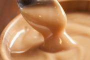
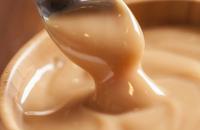
Take a ladle or saucepan and pour milk and cream into it. Add vanilla sugar (sugar with vanilla seeds). In a separate...

Hello everyone! Today we have a very tasty and simple recipe in front of us - sausages in dough in the oven. Can you smell what...

Avocado is one of the healthiest fruits. This is a real storehouse of vitamins and nutrients. And it is often...

Roast pork is an ideal tasty and satisfying dish that can feed the whole family. Housewives love roast...

This cake is very easy to make and tastes like the classic Napoleon. When making a cake there are several...

Representatives of these zodiac signs do not always become close people, but they are pleasant and interesting to each other....

Compatibility between a Rooster man and a Pig woman is based on mutual understanding between the partners. They have different personalities and...
several basic concepts and formulas. All substances have different mass, density and volume. A piece of metal...

If we’re going to talk about gender equality, then it’s with someone like an Aries woman. This emancipated lady is a bright...

The meaning of life is related to the question “What to live for”, and not to the question of how to maintain life. Attitude...

A mushroom is a living organism that forms a separate kingdom of the same name. For a long time they were classified as a kingdom...

For lovers of “quiet” hunting, mushroom season begins in early summer and lasts until late autumn. And rarely do they...
Aleshnikova, V.I. Use of professional consultants. - M.: Infra-M, 1999. - 240 p. 2. Beich, E....
Take a ladle or saucepan and pour milk and cream into it. Add vanilla sugar (sugar with vanilla seeds). IN...

Hello everyone! Today we have a very tasty and simple recipe in front of us - sausages in dough in the oven. Do you feel...